Embedded Systems IV
Communication Protocol
Embedded electronics is all about interlinking circuits (processors or other integrated circuits) to create a symbiotic system. In order for those individual circuits to swap their information,
they must share a common communication protocol.The main focus will be on SPI,UART,I2C. Serial communication is divided into two that is asynchrnous and synchronus serial communication
In serial communication, data is sent one bit at a time using one signal line, so in order for the receiving side to accurately receive the data, the sending side must know at what speed it is sending each bit.
Serial Communication
- Sends data bit by bit at one clock pulse
- Requires one wire to transmit the data
- Preferred for long distance communication
- Communication speed is slow
1.UART
A universal asynchronous receiver/transmitter (UART) is a block of circuitry responsible for implementing serial communication. Essentially, the UART acts as an intermediary between parallel and serial interfaces.On one end of the UART is a bus of eight-or-so data lines (plus some control pins), on the other is the two serial wires - RX and TX.
As the R and T in the acronym dictate, UARTs are responsible for both sending and receiving serial data. On the transmit side, a UART must create the data packet- appending sync and parity bits -
and send that packet out the TX line with precise timing (according to the set baud rate). On the receive end, the UART has to sample the RX line at rates according to the expected baud rate, pick out the sync bits, and spit out the data.
2. I2C
The Inter-Integrated Circuit (I2C) Protocol is a protocol intended to allow multiple "peripheral" digital integrated circuits ("chips") to communicate with one or more "controller" chips.It is only intended for short distance communications within a single device. Like Asynchronous Serial Interfaces (such as RS-232 or UARTs), it only requires two signal wires to exchange information.
It can support a multi-controller system, allowing more than one controller to communicate with all peripheral devices on the bus (controller devices take turns using the bus lines to talk to each other).
Data rates fall between asynchronous serial and SPI; most I2C devices can communicate at 100kHz or 400kHz. There is some overhead with I2C; for every 8 bits of data to be sent, one extra bit of meta data
(the "ACK/NACK" bit, which we'll discuss later) must be transmitted.
3.SPI
Serial Peripheral Interface (SPI) is an interface bus commonly used to send data between microcontrollers and small peripherals such as shift registers, sensors, and SD cards. It uses separate clock and data lines,along with a select line to choose the device you wish to talk to.It's a "synchronous" data bus, which means that it uses separate lines for data and a "clock" that keeps both sides in perfect sync.
The clock is an oscillating signal that tells the receiver exactly when to sample the bits on the data line. This could be the rising (low to high) or falling (high to low) edge of the clock signal;
Advantages of SPI:
- It's faster than asynchronous serial
- The receive hardware can be a simple shift register
- It supports multiple peripherals
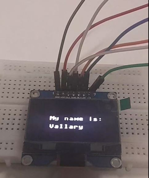
Oled display using SPI
Interfacing SSD1306 OLED Display with Raspberry Pi Pico MicroPython code is interfaced to the OLED display with the Pico board using Thonny IDE.Thonny IDE requires an SSD1306 driver code which must be written before displaying any text or graphics on the OLED display.he programming process is divided into two main parts. writing the SSD1306.py driver code and the main.py code. The SSD1306.py code should be written and uploaded first, and then the main.py code can be uploaded and run.
The code for the SSD1306.py file is responsible for setting up the OLED display and configuring it to work with the Raspberry Pi Pico. It includes library imports, initialization commands, and functions for displaying text
and graphics on the OLED screen.The main.py code, on the other hand, is where the main logic of the program resides. It also includes commands for controlling the OLED display and updating the displayed information.
Below is code for Raspberry and Oled
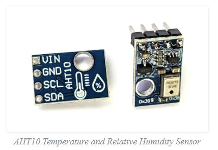
AHT10 Temperature and Relative Humidity and I2C
The AHT10 is an accurate temperature and humidity sensor in a very small package that can be accessed via an I2C interface. While it has a temperature measurement range of between -40°C and 85°C, its typical error of ± 0.3is achieved between around 0°C and 55°C.
How is the AHT10 sensor accessed? The sensor is accessed via I2C, but we can abstract the complexities of this via a pre-built MicroPython module.To make use of the module we will need to download it from GitHub and then
copy it over to our Pico. I found this most easily accomplished by first downloading the file to the main computer and then going File >> Open on Thonny and selecting the appropriate file.
From there go File >> Save as… and select the Pico as the location to save the file (making sure to save it with the appropriate name (ahtx0.py))
Connecting the AHT10 to the Pico
The connection is fairly simple with only four connections being required. Power, ground, Serial CLock line (SCL) and Serial DAta line (SDA). The following connections are used for this example;- AHT10 GND to Ground (pin 38) on the Pico (Black)
- AHT10 VIN to the 3V3(OUT) (pin 36) on the Pico (Red)
- AHT10 SCL to I2C1 SCL (pin 32, or GPIO27) on the Pico (Orange)
- AHT10 SDA to I2C1 SDA (pin 31, or GPIO26) on the Pico (Brown)